AI data centers require up to ten times more fiber than traditional compute deployments (IoT Analytics / Cables Plus USA, 2026). What is rarely explained is what it means operationally: for fiber installation planning, OTDR testing programs, splice quality standards, and the field execution teams who will install the infrastructure.
Why AI Data Centers Need So Much More Fiber
Scale-up vs. scale-out networking: AI training workloads require scale-up networking — hundreds of GPUs operating as a synchronized computing unit, connected by high-bandwidth low-latency interconnects in a flat or near-flat topology. This requires direct, high-bandwidth connections between GPU nodes — dramatically more fiber paths than traditional tree topology generates.
Speed transitions driving parallel fiber increases: The shift from 100G to 400G and 800G uses parallel optic approaches (multiple fiber paths in parallel to achieve aggregate bandwidth). A 400G connection may use 4 × 100G parallel paths, each requiring its own fiber pair. As speeds increase, fiber counts increase proportionally.
What This Means for Fiber Installation Planning
→ Pathway capacity for AI density: Overhead tray capacities designed for conventional compute are exceeded by AI fiber counts. Pathway engineering is a primary deliverable, not a detail resolved during installation.
→ Connector quality at 10x volume: Contamination in a high-density MPO/MTP array can affect 12 or 24 fiber paths simultaneously. Port inspection and cleaning must be applied consistently across every connection — not selectively.
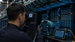
→ MPO/MTP handling protocol: Requires MPO-compatible fiber scope (standard LC/SC scopes will not inspect the multi-fiber array), MPO-specific cleaning tools, and polarity verification before every connection.
→ OTDR testing — 100% coverage, not sampling: 100% OTDR coverage establishes a clean baseline before the network activates. Sampling leaves uncharacterized fibers that produce incidents after activation. With the right equipment, 100% coverage at AI fiber density is achievable within field timelines.
The Structured Cabling Standard for AI Data Centers
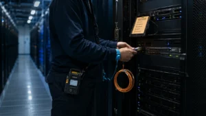
At AI fiber density, labeling consistency is operationally critical. Unlabeled or inconsistently labeled fiber paths in a dense GPU interconnect plant make moves, adds, and changes error-prone — and errors in GPU fabric cabling produce performance impacts that take hours to correlate back to a physical problem.
Fiber type selection: OS2 single-mode for optical transport interconnects and long-reach DCI; OM3/OM4 multimode for intra-rack and short-reach parallel optic connections at 100G-SR4, 400G-SR4, and 800G-SR8. Minimum bend radius must be maintained at every transition — AI-density cable plants are more susceptible to macro-bending loss.
Documentation: The as-built must include complete port mapping, fiber type per path, OTDR test results per fiber, MPO polarity confirmation per trunk, and pathway routing for each bundle — the reference for all future modifications.
How to Plan a Fiber Installation Program for AI Infrastructure
Five specification decisions that need to be locked before mobilization — not resolved in the field.
FREQUENTLY ASKED QUESTIONS
Two reasons: scale-up GPU interconnect topology requires direct high-bandwidth connections between GPU nodes (many more fiber paths than tree topology); and high-speed parallel optic connections (400G-SR4, 800G-SR8) use multiple fiber lanes per logical connection, multiplying fiber count as speeds increase.
100% coverage — every fiber tested, bidirectionally, at the appropriate wavelengths (1310 nm and 1550 nm for single-mode), before the network activates. Sampling-based testing leaves uncharacterized fibers that produce incidents after activation.
MPO/MTP requires: an MPO-compatible fiber scope for end-face inspection, MPO-specific cleaning tools, polarity verification (Type A/B/C polarity affects how fiber paths align), and confirmation that the connector seats fully with the latch engaged.
Complete port mapping (every port to its connected device), fiber type per path, OTDR test results per fiber (bidirectional), MPO polarity confirmation per trunk, labeling convention as-installed, and pathway routing documentation per bundle.